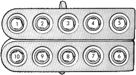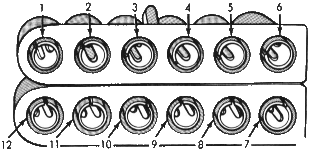
[ 10 Way Connector | 12 Way Connector ]
This page contains information specific to the 1985 through 1987 power modules used on all 2.2L and 2.5L throttle body fuel injected engines. If you are not familiar with what the power module is, please see the Understanding The Chrysler Engine Control Unit page before reading this one.
The power module has two connectors with large pins (a 10-way and a 12-way). The following sections contain a diagram and pin-out for each. The wire colors are in the color/tracer* format (BK/WT* = black wire with a white tracer). Below is a list of color abbreviations:
| Code | Color | Code | Color | Code | Color |
| BK | Black | LB | Light Blue | TN | Tan |
| BR | Brown | LG | Light Green | VT | Violet |
| DB | Dark Blue | OR | Orange | WT | White |
| DG | Dark Green | PK | Pink | YL | Yellow |
| GY | Grey | RD | Red | * | tracer |

| Pin | Circuit | Wire Gauge | Wire Color | Function |
| 1 | J5 | 18 | BK/YL* | Ignition Coil driver output |
| 2 | J2 | 14 | DB | 12V power feed from ignition switch "run" and "start". |
| 3 | K14 | 18 | DB/WT* | 12V power feed to logic module (from J2) |
| 4 | J1 | 12 | PK | Direct battery feed |
| 5 | K18 | 18 | TN | Fuel Injector driver output |
| 6 | Z1 | 14 | DG/BK* | ASD relay power output |
| 7 | K17 | 18 | WT | Fuel Injector driver output |
| 8 | R3 | 18 | DG | Alternator Field Coil driver output |
| 9 | J9 | 16 | Bk | Engine ground at top rear of engine |
| 10 | J9 | 16 | BK | Engine ground at top rear of engine |

| Pin | Circuit | Wire Gauge | Wire Color | Function |
| 1 | K16 | 22 | VT/YL* | Fuel Injector control signal from logic module |
| 2 | Y5 | 18 | BK/LB* | Signal ground from logic module |
| 3 | K22 | 22 | RD/BK* | A/C cutout relay signal |
| 4 | - | - | - | Not used |
| 5 | K19 | 20 | DB/YL* | Battery temperature sensor output signal |
| 6 | J11 | 20 | RD/WT* | Direct battery feed to logic module |
| 7 | - | - | - | Not used |
| 8 | - | - | - | Not used |
| 9 | - | - | - | Not used |
| 10 | K15 | 22 | YL | Anti dwell control signal from logic module |
| 11 | R31 | 22 | DG/OR* | Voltage regulation signal from logic module |
| 12 | N6 | 18 | OR | 7.5V power feed to logic module |
| Return to the Engine Control Unit page |
Updated 12/07/2004.
Copyright © 1996-2004 Russ W. Knize.