Installing A Zener Diode On The MAP Sensor
Description
Here is my procedure on how to install a zener diode on your MAP sensor,
to limit its output and avoid overboost shutdown. This procedure
requires that you have a very basic knowledge of electronics. Although
this mod is easy, I would recommend using Gus's Map
Sensor Bleed over this setup. I did not invent this design, but
rather it is a common way to circumvent the ECU`s boost measurements.
Procedure
-
You will need either a 4.3V or 4.7V zener diode. Use the chart below
for part numbers. The industry part number is 1N749A or 1N750A for
the 500mW device. These are low tolerance parts (designated by the
"A", which means +/- 5%), which equals about 0.47V variation between parts.
It would be better to get a higher tolerance part, if possible (1N749C
or 1N749D), but these are difficult to find. If you cannot find a
better part, then get a few of them so you can mix and match to find one
that works well for you.
-
Locate your MAP sensor. On all vehicles before 1987 and all L-bodies
(Omni/Horizon and Charger/Turismo), the sensor is located on the logic
module. Later models (except L-body) located the MAP sensor on the
front of the right, front shock tower with the baro-read solenoid.
For sensors located on the logic module, you will have to remove the sensor
from the module to get at the short harness inside.
-
The center wire is the signal output, which is either white (WT) or dark
green with a red stripe (DG/RD*). The other two wires are 5V and
ground. You also need to find the ground wire, which is either black
(BK) or black with a light blue stripe (BK/LB*).
-
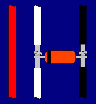
You will need to connect the zener diode with the anode on the ground wire
and the cathode on the signal output wire. The cathode is the side
with the lead near the stripe. Strip the insulation off of part of
the wires and solder the diode into place. See below:
Overboost Cut-off Points by Year, Engine, and Transmission
|
Year
|
Engine
|
Manual
|
Auto
|
|
1984
|
Turbo I
|
4.30V
|
4.30V
|
|
1985
|
Turbo I
|
4.54V
|
4.65V
|
|
1986
|
Turbo I
|
4.65V
|
4.88V
|
|
1987
|
Turbo I
|
4.65V
|
4.88V
|
|
1987
|
Turbo II
|
4.65V
|
-
|
|
Zener Diode Part Numbers
Zener
Voltage
|
Industry
Part Num
|
Radio
Shack
|
|
4.3V
|
1N749
|
RSU 11928561
|
|
4.7V
|
1N750
|
-
|
|

Now, your MAP sensor output will be limited to around 4.3V or 4.7V (depending
which zener and what tolerance you have). To make sure that your
installation has been successful, you can put a volt meter across the diode
with the ignition on and pressurize the MAP sensor (don't exceed about
30 psi). The voltage will rise until it hits the cut-off (zener)
voltage of the diode. Then, the diode shorts out and limits the voltage.
The highest voltage you see is the zener voltage for this diode.
You can now test your setup by driving it around. Remember that
you will lean out when the pressure generates a voltage past the zener
point of the diode, so you need to keep your bleeds low at first and watch
your A/F very closely. If the poor tolerance of the diode allows
the voltage to get too high, you may get overboost shutdown anyway.
If this happens, try swapping it with another diode and test it to see
if your get a lower voltage than before. The better diodes shouldn't
have this problem.
This page is maintained by Russell W. Knize and was last updated 04/27/99.
Comments? Questions? Email
minimopar@myrealbox.com.
Copyright © 1996-2003 Russ W. Knize

