Wastegate Control Bleed Boost Peak Suppression
Description
This page describes a method to help eliminate the problem boost peaks
(or "spikes") when using wastegate control bleeds (WCBs). To read
more about WCBs, see the Increasing Boost With Wastegate
Control Bleeds page. The primary problem with bleeds is boost
peaking. This happens because of the delay between the rise in manifold
pressure and the pressurization of the wastegate actuator can. The
bleed slows this pressurization and the wastegate is not opened fast enough.
Once the pressure in the actuator has "caught up" the boost drops back
down and stabilizes. This is especially apparent with smaller turbochargers
(Mitsubishi TD04) because they respond very fast compared to the Garrett
turbos. Also, the smaller turbos tend to suffer from "boost creep"
at lower engine speeds when using a stock exhaust system. This is
because the stock exhaust system is less restrictive when the exhaust gasses
are moving slower (because of the slower engine speed), but the turbo is
able to generate a lot of boost because if it's smaller size.
The way this system works is to eliminate this boost peak by installing
a solenoid controlled by a pressure switch or an Electronic
Engine Performance Controller (EEPC) to pressurize the wastegate actuator
quickly and open the wastegate. This causes the boost to drop back
down to the point that the bleed was set for. It will also prevent
boost creep, but will end up turning the solenoid on and off as the boost
drops and then tries to rise again. This will result is boost oscillation,
where the boost pressure varies up and down once every second or so.
I highly recommend using wastegate control valves (WCVs) over wastegate
control bleeds (WCBs) because they virtually eliminate boost peaking and
creeping, even with small, responsive turbochargers. See the Increasing
Boost With Wastegate Control Valves page.
Using A Pressure Switch
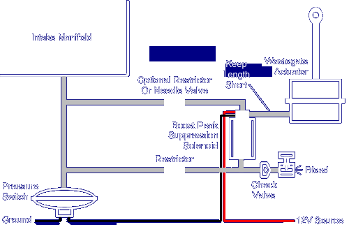
Using a pressure switch for this is quite simple. Install a solenoid
in parallel with the restricted line the leads to the bleed. The
common barb on the solenoid will be connected to the wastegate actuator
so that the solenoid will switch between the bled line and the direct line.
For more information on solenoids, see the
Understanding
Solenoids page. Your configuration will then be something like
this:

To calibrate this setup, you need to set the pressure switch to turn
on at your absolute maximum boost setting. This should just above
the setting of your bleed. If you adjust it too close, you may get
boost oscillation. If you have overboost shutdown problems, then
set it to be just below your overboost shutdown (typically around 14.3psi).
Using The EEPC
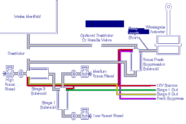
The configuration for adding the quick pressure release feature with an
EEPC is basically the same. The only difference is that the solenoid
is activated by the circuit instead of pressure switch. I trust that
you can envision this minor change. Since the EEPC is generally used
for multi-stage WCBs, I have provided a diagram for a 3-stage WCB with
boost peak suppression. As with most EEPC setups, the EEPC circuit
provides the ground to the solenoids, so each solenoid needs a common 12V
source. It's always a good idea to put a small fuse on this line,
close to the power source. About 1A should work.

The calibration procedure for this setup is the same as the pressure
switch. You want to EEPC output for the peak suppression to your
absolute maximum boost setting. This should just above the setting
of your high boost needle valve. If you adjust it too close, you
may get boost oscillation. If you have overboost shutdown problems,
then set it to be just below your overboost shutdown voltage (typically
around 4.9V). For more information about install the EEPC, see the
Multi-Stage
Wastegate Control Bleed Using The EEPC page.
This page is maintained by Russell W. Knize and was last updated 04/21/99.
Comments? Questions? Email
minimopar@myrealbox.com.
Copyright © 1996-2003 Russ W. Knize


