The logic module (whether stock or performance) is designed to bring up boost levels at a slow rate by opening the wastegate at about 3-4 psi. This is to make the engine response more smooth and managable to the common driver. As you probably know, the high torque of the engine tends to "kick in" at a certain rpm range. If the logic module didn't suppress the boost inrease, the engine would "kick" even harder. This also prevents the boost level from peaking, which is when it momentarily goes over the desired limit.
Taking control of the wastegate does not take away to ECU's ability
to safely operate the engine. If the boost climbs too high (past
the overboost shutdown point), the ECU will shut the engine down.
If the engine is knocking, it will retard the timing. You should
retard the base timing some (to about 10 degrees, advanced) and use higher-octane
gas, since the logic module would normally reduce boost if the engine was
knocking badly. Since the boost level is not allowed to exceed the
shutdown point, the logic module
always knows how much air is going into it and therefore will never let
the engine run lean (unless you have a weak fuel system - see
Diagnosing
Your Fuel System). The
Engine Information
page describes this further. You can check the status of your engine
during boost by installing an A/F guage, or connecting
a volt meter to your oxygen sensor output line. If the voltage is
above 0.8V (8 lights), then you are OK. Above 0.9V (9 lights) is
preferred.
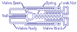
If you are not going to drill into the valve, there is no reason to switch the valve and spring inside. however, since all of the other documentation on the web shows the ball and spring switched, this page conforms to this as well. So when you get the valve, you need to unscrew the knob completely, remove the ball and spring, put the ball into the valve body first, and then the spring. Once this is done, your valve will be configured like this:

Rather than using plastic and glue, I opted to solder on brass hose barbs for a more secure design. I used two 3/16" hose barb to 1/8" pipe thread adapters. I machined the threaded side off leaving about 3/16" of the hex body remaining. I then machined about 1/16" of the remaining body down to a 0.285" lip, which fits perfectly into the bore of the valve. I then soldered one on each side of the valve. Be sure to sand the soldering surface of the valve before soldering it.

Gus's design requires drilling into the valve and using epoxy to glue in plastic hose barbs. The diameter of the hole to dril depends of the hose barbs you get. Measure twice, cut once. The barbs can be cut off of a plastic 5/32" I.D. vacuum hose "T" fitting. This method seems to work just fine, though you need to be careful not to drill all the way through the valve body or you will destory the ball valve seat. Also in this case, you have to switch the ball and spring around as shown in the above diagram because you have to drill completely through the knob to secure the plastic host barb well. Be sure not to allow the barb on the knob to protrude into the valve and try to keep the epoxy out of the valve and barb. Using this method, the valve will be configured like this:

Boost Controller, by Gus Mahon
Dempsey also has a page on it, which you should check out:
Using A Grainger Valve To Control Boost, by Dempsey Bowling
To learn about the WCV Quick Pressure Release, see my page on it:
WCV Quick Pressure Release, by Russ
W. Knize
Multi-Stage WCV Using The EEPC,
by Russ W. Knize
| Return to the Mini-Mopar Turbo Performance page |
This page is maintained by Russell W. Knize and was last updated 04/20/99. Comments? Questions? Email minimopar@myrealbox.com.
Copyright © 1996-2003 Russ W. Knize